Buyer Guide · Testing

How to Read a Fiber Patch Cord Test Report: Insertion Loss, Return Loss and Grades

A patch cord test report lists, for each serial number, the insertion loss (IL) and return loss (RL) of each connector at each test wavelength, together with the limit applied and the method used. IL is measured to IEC 61300-3-4 and should be low; RL is measured to IEC 61300-3-6 and should be high. Read a report by checking four things: that every cord and every end has its own values, that the wavelengths match the fiber (1310 and 1550 nm for singlemode, 850 and 1300 nm for multimode), that the limits match your order, and that the reference method and test equipment are named. A report that only says "PASS" does not let you check any of that.

Published 2026-11-12 · Updated 2026-11-12 · By the Lumafyn Technical Team

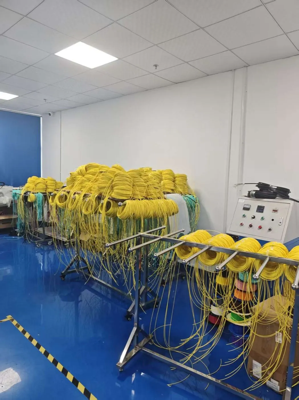
Yellow fiber patch cords hanging on work-in-process racks next to test equipment

Insertion Loss and Return Loss in Plain Terms

Insertion loss is the light lost through a connection, in dB. Lower is better: 0.20 dB means about 4.5% of the light is lost. Return loss is how strongly the connection reflects light back toward the source, also in dB, and here higher is better: 55 dB means much less reflected light than 35 dB. Reflection matters for singlemode lasers, video overlay on PON and high-speed links, which is why RL is reported for singlemode cords and usually not for multimode.

Polish drives return loss. A UPC (domed, flat contact) singlemode connector typically reflects more than an APC connector, whose 8° angle sends reflected light into the cladding. That is why APC connectors are used where reflection limits are strict.
The Fields a Useful Report Contains

Patch cord test report fields and what to check
FieldWhat it tells youWhat to check
Serial number or line IDWhich physical cord the values belong toMatches the label on the cord bag
Connector and polish per endFor example LC/UPC to SC/APCSame as the order line; APC ends have APC-level RL
Fiber type and lengthOS2, OM4 and so on; ordered lengthMatches the order
WavelengthsTest wavelengths in nm1310 and 1550 nm for singlemode; 850 and 1300 nm for multimode
IL per end, per wavelengthLoss of end A and end B against the referenceEach value under the agreed limit
RL per end (singlemode)Reflectance of each connectorEach value above the agreed limit
Limits appliedThe pass/fail values usedSame as the specification in your order
Reference methodReference cord or reference-grade connector usedStated, not left blank
Test set and calibrationInstrument model and calibration dateCalibration in date on the test date
Date and operatorWhen and by whomConsistent with production dates
End-face inspectionPass/fail to IEC 61300-3-35Present if you asked for it
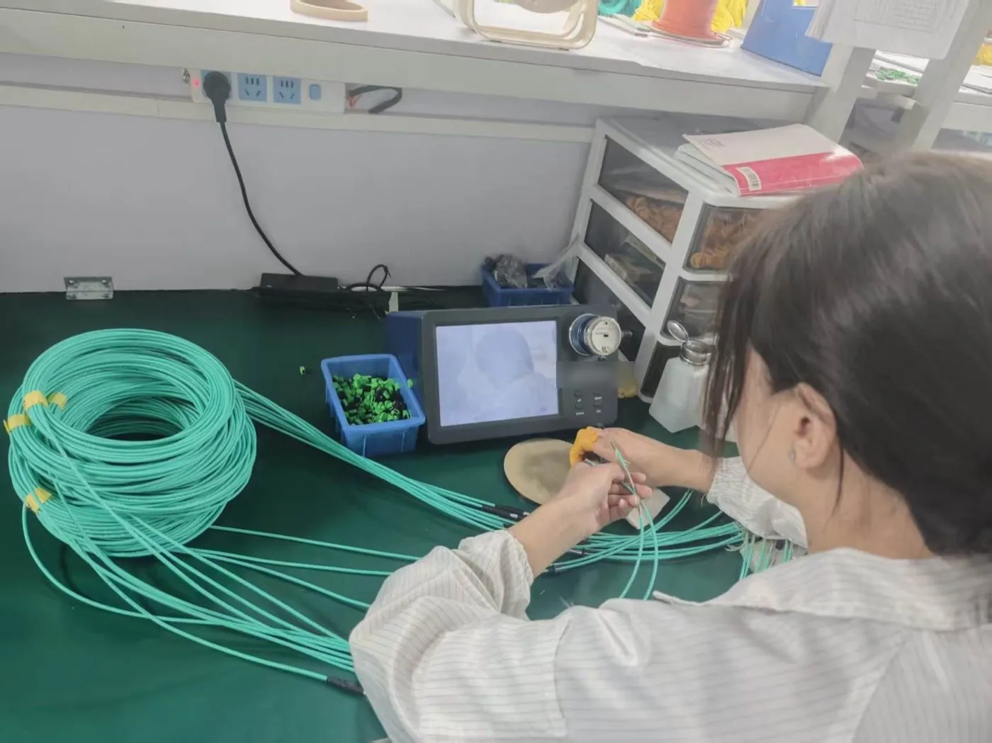
End-face inspection workbench with a fiber microscope in our own factory

Test Methods: IEC 61300-3-4 and IEC 61300-3-6

IEC 61300-3-4 covers attenuation (insertion loss) measurement. For factory testing of cords, the usual approach is to connect the cord under test to a reference cord from a stabilized light source and measure the power at a meter, after first setting a zero with the reference alone. The value printed for "end A" is therefore the loss of a mated pair: the cord's connector plus the reference connector. That is why the reference method matters. A reference-grade connector adds very little loss of its own, and IEC 61755 defines reference grades for this purpose.

IEC 61300-3-6 covers return loss measurement. Factory test sets typically use an optical continuous wave reflectometer (OCWR) or an OTDR-based method, with the far end of the cord terminated so that its own reflection does not add to the reading. For the field side of testing, the Fiber Optic Association's guide to OFSTP-14 and similar procedures explains how reference choices change results.

Neither method can see dirt that arrives after testing. A report shows the cord was within limits when it was tested and capped; inspect before mating on site, as described in our MPO/MTP inspection and cleaning guide.

Which Limits Are Reasonable to Ask For

Limits come from the standard named in your specification or from the supplier's product specification. The two references most buyers meet are ANSI/TIA-568.3-D for cabling and IEC 61753-1 for connector performance grades.

Common reference values (from ANSI/TIA-568.3-D and IEC 61753-1 as published by connector makers)
ReferenceInsertion lossReturn loss
ANSI/TIA-568.3-D, mated connector pairMax. 0.75 dBMin. 35 dB singlemode, min. 20 dB multimode
IEC 61753-1 grade B (singlemode)Max. 0.12 dB mean, max. 0.25 dB for at least 97% of random matingsSee RL grades
IEC 61753-1 grade C (singlemode)Max. 0.25 dB mean, max. 0.50 dB for at least 97%See RL grades
IEC 61753-1 grade D (singlemode)Max. 0.50 dB mean, max. 1.00 dB for at least 97%See RL grades
IEC 61753-1 RL grade 1 (singlemode)—Min. 60 dB mated, min. 55 dB unmated (APC)
IEC 61753-1 RL grade 2 / 3 / 4—Min. 45 dB / 35 dB / 26 dB
IEC 61753-1 grade Bm / Cm (multimode, 850 nm)Max. 0.3 dB mean, 0.6 dB for 97% / max. 0.5 dB mean, 1.0 dB for 97%RL grade 2m: min. 20 dB

Two cautions. First, IEC grades are defined for random mating of connectors, which is measured to IEC 61300-3-34 on a population; a single factory reading against a reference cord is not the same test, so a report showing "0.15 dB" does not by itself prove grade B. Second, TIA-568.3 values are cabling limits for installed links, so they are useful as a ceiling, not as a target for new cords. If you need a grade, write the grade and the verification method into the order.

Reading an Example Line

The table below is an illustrative example of a report layout, not test data from any real cord or order.

Illustrative test report line (not real test data, not a real order)
FieldExample entryHow to read it
SerialEXAMPLE-0001Must match the cord label
ConfigurationLC/UPC to SC/APC, OS2, simplex, 3 mMixed polish: expect different RL per end
IL end A, 1310 / 1550 nm0.18 / 0.16 dBBoth under a 0.30 dB limit
IL end B, 1310 / 1550 nm0.21 / 0.19 dBBoth under a 0.30 dB limit
RL end A (UPC)52 dBAbove a 50 dB UPC limit
RL end B (APC)63 dBAbove a 60 dB APC limit
LimitsIL max. 0.30 dB; RL min. 50 dB UPC, 60 dB APCThe buyer and supplier agreed these values
MethodIEC 61300-3-4 reference cord method; IEC 61300-3-6 OCWRMethod named
EquipmentTest set model, calibration dateIn calibration on the test date

On a real report you would check each of these against your order line. The patch cord buying guide shows how to write connector, polish and fiber fields so that the report can be compared with the order.

Red Flags on a Test Report

  • Only "PASS" with no values. You cannot check limits, wavelengths or ends.
  • Identical values on many cords. Real measurements vary; a column of 0.20 dB on every line suggests values were copied, not measured.
  • One wavelength only for singlemode. 1550 nm shows bend-related loss that 1310 nm can miss; most specifications ask for both.
  • Values that beat the measurement. Negative IL or 0.00 dB readings point to a reference problem; ask how the zero was set.
  • APC ends with UPC-level RL. An APC connector reading in the 40s or low 50s dB suggests a polish, cleaning or measurement problem.
  • No serial numbers. Without traceability a report cannot be linked to the cords you received.
  • No method or calibration date. The numbers cannot be reproduced or compared.

When a value looks wrong, ask for a re-test of a sample on arrival with your own equipment and a reference cord of known quality. Our fiber optic quality control guide covers sampling and pre-shipment inspection.

Asking for the Right Report in an RFQ

Write the report requirement per line so it travels with the order. The lines below are an example of the format, not a real order.

Example test report requirements on an RFQ (not a real order)
LineExample
PC-01, Vancouver enterpriseLC/UPC duplex, OS2, 2.0 mm, OFNR, 2 m
Optical testIL per end at 1310 and 1550 nm, max. per agreed specification; RL per end, min. per agreed specification
Report formatPer serial number, Excel or PDF, with method, equipment and calibration date
InspectionEnd-face pass/fail to IEC 61300-3-35 per connector
CommercialQuantity per line and required date

Our patch cord wholesale and OS2 LC to LC patch cord pages list the cord types we quote. Optical values and the report format for your order are confirmed in the quotation and the test records shipped with it.

FAQ

Patch Cord Test Report FAQ

What is a good insertion loss for a patch cord?

It depends on the specification you buy to. TIA-568.3-D allows up to 0.75 dB per mated pair in installed cabling; many cord specifications use much tighter per-connector limits. Agree the limit and method in the order.

Why is return loss higher for APC than UPC?

The 8° angle of an APC end face sends reflected light into the cladding instead of back down the core, so less light returns to the source and the RL value in dB is higher.

Is IL measured for each end of a cord?

On a useful report, yes. Each connector is measured against a reference, so a cord has an end A and an end B value at each wavelength.

Do multimode cords need return loss values?

Often not. Reflection matters less for multimode links, and TIA-568.3-D sets only a 20 dB minimum. Some projects still ask for it.

Does a test report prove an IEC 61753-1 grade?

Not on its own. Grades are defined for random mating across a population, measured to IEC 61300-3-34. Ask how the grade is verified if you need one.

Sources and Further Reading

Standards and public references describe definitions and industry practice; they are not Lumafyn product data. Optical values, MOQ and lead time for your order are confirmed in your quotation and test records.

Related products and guides

Get a Quote