Buyer Guide · ODF & Patch Panels

ODF and Fiber Patch Panel Buying Guide: Panels, Modules and Cassettes

A fiber patch panel or ODF (optical distribution frame) is specified correctly when you define five things together: mounting format, port capacity, adapter interface, how fibers are terminated behind the panel (splicing, pigtails or MPO cassettes) and how the panel is labeled and accessed. This guide walks through each decision, shows the line format we use to quote ODF orders, and lists the inspection checks worth asking for before shipment.

Published 2026-07-18 · Updated 2026-11-10 · By the Lumafyn Technical Team

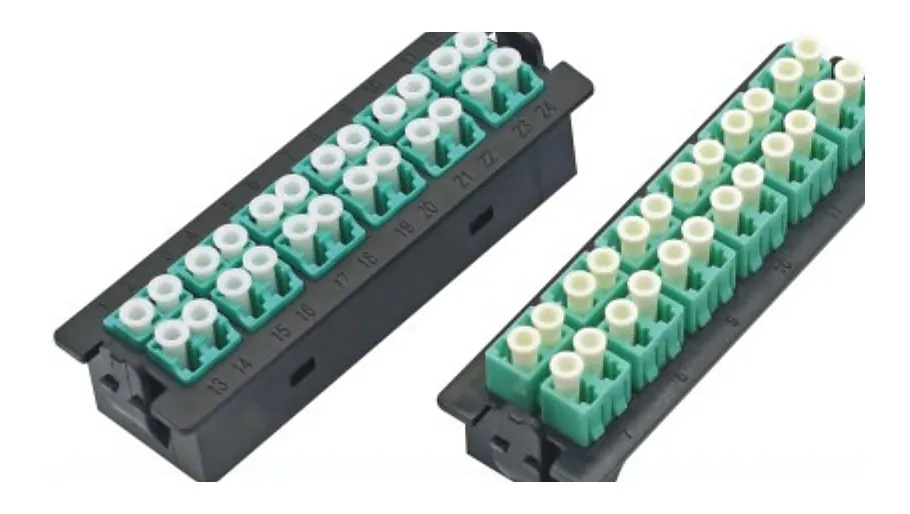
Two fiber adapter panels with rows of aqua and green LC duplex adapters

ODF, Patch Panel, Module or Cassette: What Is the Difference?

The terms overlap, so it helps to agree on them before writing an RFQ. In this guide:

Fiber distribution hardware types
HardwareWhat it doesTypical location
ODF (optical distribution frame)Terminates incoming cable fibers, usually by fusion splicing to pigtails, and presents them on adapters for cross-connectTelecom central office, equipment room, FTTH distribution point
Rack-mount fiber patch panelPresents adapters on the front of a 19-inch rack unit; may hold splice trays, pre-terminated pigtails or cassettes behindEquipment room, enterprise or data center rack
Wall-mount box / terminal boxSmaller enclosure for splicing and patching where there is no rackBuilding entry, MDU floor, outdoor cabinet
Adapter panel (plate)A loaded faceplate of adapters that clips into a panel or chassis slotInside modular panels and ODFs
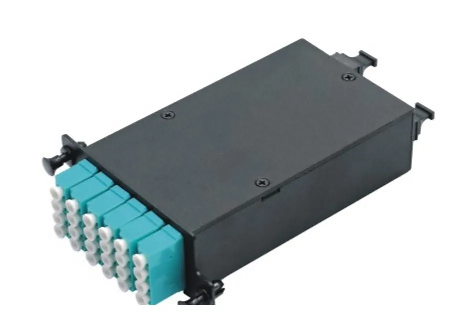
MPO/MTP cassette (module)Breaks an MPO trunk out to LC or SC ports inside a sealed moduleHigh-density data center panels

Most buyers need a combination: a chassis or frame, the adapter plates or cassettes that load it, and the fibers that feed it. Quoting them as one connected bill of materials avoids the common problem of a panel arriving with the wrong adapter count or a cassette that does not fit the chassis slot.
Step 1: Mounting Format and Space

Start with where the hardware will live, because it fixes the outer dimensions.

  • Rack mount. Standard panels fit 19-inch racks (EIA-310). Height is stated in rack units: 1U is 1.75 in (44.45 mm). State how many U you can spare and whether the rack is two-post or four-post.
  • Wall mount. Give the available wall area and whether the box must lock.
  • Cabinet or frame. For an existing ODF frame or outdoor cabinet, send the frame model or a drawing with internal dimensions.
  • Access direction. Say whether technicians work from the front only, or also from the rear. Sliding-drawer panels help where rear access is limited.

If the panel will sit next to existing hardware, a photo of the rack with a tape measure in frame often answers more questions than a written description.

Step 2: Port Capacity, Active Ports and Growth

"24-port ODF" is a starting point, not a specification. Separate three numbers in your RFQ:

  1. Active ports today – the connections that will be patched at installation.
  2. Total termination capacity – the number of fibers the panel must be able to terminate, including spares.
  3. Growth plan – whether empty positions are for a later phase, a spare route or not needed at all.

Port count also depends on the adapter style. A duplex LC adapter carries two fibers in roughly the space of one SC simplex adapter, which is why high-density 1U panels are almost always LC. Ask for the panel's port count in the adapter type you actually need rather than assuming the brochure maximum applies.

How the adapter choice changes capacity
Adapter on the panelFibers per adapterTypical use
SC simplex1FTTH and telecom ODFs, APC polish common
SC duplex / LC quad footprint2–4Mixed telecom and enterprise panels
LC duplex2Enterprise and data center panels
MPO/MTP cassette (12 or 24 fiber)12 or 24 behind one moduleData center trunks broken out to LC

Step 3: Adapter Interface, Polish and Fiber Type

Every adapter line should state connector family (LC, SC, FC, ST or MPO), simplex or duplex, polish (UPC or APC) and fiber mode. Adapter housings follow common color conventions that make mistakes visible on site: blue for singlemode UPC, green for singlemode APC, and beige, aqua or other colors for multimode. Treat colors as a convention to confirm on your drawing, not as a guarantee across all brands.

APC and UPC connectors must never be mated with each other; the 8° angled end face of an APC connector does not meet a flat UPC end face correctly and the link will show high loss and reflection. If the panel serves both FTTH (usually SC/APC) and equipment links (often LC/UPC), list them as separate adapter lines with their own quantities.

Step 4: How Fibers Reach the Back of the Panel

The rear side is where most quotation errors happen. Choose one of three approaches and state it per panel line:

Termination options behind an ODF or patch panel
MethodWhat to specifyNotes
Fusion splice to pigtailsSplice-tray count and capacity, pigtail connector/polish, fiber type, pigtail length and color orderClassic ODF build; pigtails usually follow the TIA-598 12-color sequence
Pre-terminated pigtails or patch cordsConnector at each end, length from panel to equipment, labelsFaster on site; length schedule must be correct
MPO/MTP cassettesCassette fiber count, MPO gender and key orientation, polarity method, front port typeMust match the trunk cable and the chassis slot
Feed-through onlyAdapter count and type; no internal fiber managementPatch cords plug into both sides

For splice ODFs, also list cable entry (top, bottom or rear), the cable diameter, and whether you need strain-relief and grounding hardware for armored or outdoor cable. For cassette panels, link the panel line to the MPO/MTP trunk cable that will plug into it and state the polarity method; see the MTP/MPO polarity guide if the method is not yet fixed.

Black MPO to LC module box with a row of aqua LC duplex adapters on the front

Step 5: Port Labels, Front-to-Rear Path and Change Control

A panel is only as useful as its records. Ask for a port-numbering scheme that matches your drawing, and keep one path record per connection: the front port label, the rear cable or fiber it connects to, and any splice tray, pigtail or cassette in between. TIA-606 (Administration Standard for Telecommunications Infrastructure) is the usual reference for label formats if you do not already have a house standard.

When a project changes, issue the change as a new BOM revision rather than an email note. State which line changed, the old and new values, and whether adapters, pigtails or labels are affected. A port-count change almost always changes the adapter plates and pigtail quantity too.

A Quote-Ready ODF Line Schedule

This is the format we use internally when a buyer sends an ODF or patch panel request. One row per distinct configuration; related items reference the parent panel line.

ODF and fiber patch panel RFQ fields
FieldWhat to sendExample
Line ID and revisionYour line number and BOM/drawing revisionODF-01, Rev B
HardwarePanel, frame, wall box or chassis; mounting format and height19-inch rack, 1U sliding drawer
CapacityActive ports, total termination capacity, spares24 active / 48 capacity
AdaptersType, simplex/duplex, polish, fiber mode, quantitySC/APC simplex, singlemode, 48
Rear terminationSplice trays and pigtails, pre-terminated cords or cassettes4 trays, 48 SC/APC pigtails, 12-color
Cable entryDirection, cable diameter, strain relief, groundingRear entry, armored, with grounding lug
LabelsPort numbering scheme and label textTIA-606 style, per drawing
Connected linesLine IDs of related trunks, patch cords or splittersMPO-03, PC-07
CommercialQuantity, packing, destination country20 sets, export carton, Canada

Optical values for any pigtails or cassettes, MOQ and lead time are confirmed in your quotation; we do not publish fixed figures because they depend on the exact configuration.

Quality Checks to Request Before Shipment

Panels are mechanical products, but they carry optical parts. These checks are reasonable to request on an ODF order:

  • Model, rack height, capacity and adapter type match the approved schedule.
  • Adapter color, polish and quantity match the BOM; no mixed APC/UPC on one plate unless specified.
  • Pigtail connector, polish, fiber type, length and color order checked before splicing or packing.
  • End-face inspection of factory-terminated connectors (IEC 61300-3-35 is the common inspection reference), with insertion and return loss records where the order includes pigtails or cassettes.
  • Front-panel labels, port numbering, carton marks and packing list checked against the drawing.
  • Photos of finished panels and packed cartons for mixed or private-label orders.
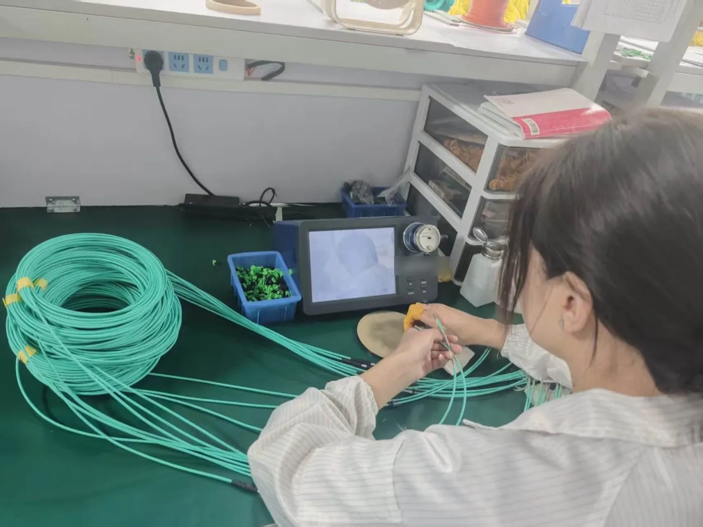
Technician checking an aqua patch cord end face with a video inspection scope at a workbench

For more detail on inspection records, see our fiber optic quality control guide.

Common ODF RFQ Mistakes

  • Port count without the interface. "48 ports" can mean 48 SC simplex or 24 LC duplex; the hardware is different.
  • "Panel with accessories." Pigtails, splice trays and adapter plates need their own lines and quantities.
  • Mixing unlike panels in one line. Separate lines whenever mounting, adapter type, access direction or the connected cable differs.
  • No rear-side plan. Without stating splice, pre-terminated or cassette, two suppliers will quote two different products.
  • Changes by email. Re-issue the BOM with a revision letter so the quote matches the latest design.

FAQ

ODF and Fiber Patch Panel FAQ

What is the difference between an ODF and a fiber patch panel?

An ODF is a distribution frame that usually terminates cable fibers by splicing them to pigtails and presents them for cross-connection, mainly in telecom and FTTH networks. A fiber patch panel is a broader term for any rack or wall unit that presents adapters; it may contain splice trays, pre-terminated cords or MPO cassettes.

How many ports fit in a 1U fiber patch panel?

It depends on the adapter. Common 1U panels carry 24 SC simplex or 24 LC duplex adapters (48 fibers), and high-density LC or MPO cassette designs carry more. State the adapter type and fiber count you need and ask the supplier to confirm the port count for that exact configuration.

Should I choose SC/APC or LC/UPC adapters?

Match the connectors already used on the link. FTTH and PON networks commonly use SC/APC; enterprise and data center equipment links commonly use LC/UPC. APC and UPC must not be mated with each other, so list them as separate adapter lines if a panel needs both.

Do I need splice trays in my ODF?

Only if fibers will be fusion-spliced inside the panel. If you use pre-terminated cords or MPO cassettes, splice trays are not needed. State the method per panel line so the quotation includes the right internal parts.

What documents should I send with an ODF RFQ?

A BOM with line IDs and revision, a rack or wall drawing, the port-numbering scheme, and the line IDs of connected trunks, pigtails or patch cords. Photos of the existing installation help when the panel must match current hardware.

Sources and Further Reading

Standards and public references describe definitions and industry practice; they are not Lumafyn product data. Optical values, MOQ and lead time for your order are confirmed in your quotation and test records.

Related products and guides

Get a Quote