Application Guide · Parallel Optics

SR4 MPO Polarity: Which Cords and Trunks Connect 40G/100G SR4 Ports

SR4 MPO polarity comes down to one rule: the transmit fiber in position 1 at one SR4 transceiver must arrive at a receive position at the other end, which in practice means position 1 lands on position 12. For a direct link, that is a single Type B MPO-12 cord with unpinned (female) ends. Through patch panels, use either Method B (Type B cords, Type B trunk, key-up to key-up adapters) or Method A (Type A trunk with one Type A and one Type B cord). This guide shows why, how to check a drawing before ordering, and what to write on the RFQ.

Published 2026-11-10 · Updated 2026-11-10 · By the Lumafyn Technical Team

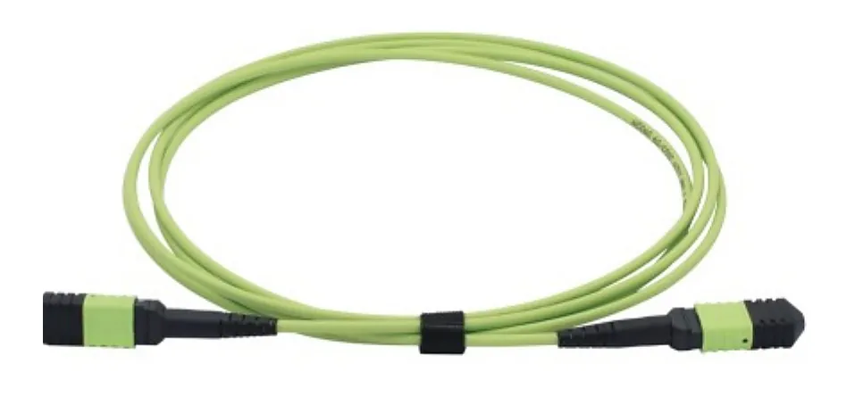
MTP/MPO trunk cable with multi-fiber connectors

How an SR4 Port Uses the MPO-12 Interface

40GBASE-SR4 and 100GBASE-SR4 are parallel optics: four lanes, each on its own fiber in each direction, for eight fibers in total. The port is an MPO-12 receptacle. According to Fluke Networks' summary of the interface, the transceiver transmits on positions 1 to 4 and receives on positions 9 to 12; the four center positions (5 to 8) are not used.

Because each lane is a separate fiber, the cabling must deliver position 1 to position 12, position 2 to position 11, and so on. If the link is wired straight through (1 to 1), transmitters face transmitters and the link stays down, even though every connector is clean and the loss is low.

SR4 interfaces at a glance (IEEE 802.3, as summarized by the TIA Fiber Optics Tech Consortium)
InterfaceFibers usedReach on OM3Reach on OM4Channel insertion loss (max)
40GBASE-SR4 (IEEE 802.3ba, clause 86)8 of MPO-12100 m150 m1.9 dB (OM3) / 1.5 dB (OM4)
100GBASE-SR4 (IEEE 802.3bm, clause 95)8 of MPO-1270 m100 m1.8 dB (OM3) / 1.9 dB (OM4)
400GBASE-SR4.2 (IEEE 802.3cm, clause 150)8 of MPO-12, bidirectional70 m100 m (150 m on OM5)1.7 / 1.8 / 2.0 dB (OM3 / OM4 / OM5)

The loss column matters for polarity planning too: every adapter you add to fix or route a link uses part of a budget that is under 2 dB for the whole channel. 400GBASE-SR4.2 runs on the same type of 8-fiber MPO cabling as 40G and 100G SR4, so a plant built correctly for SR4 can usually carry it; confirm against the module data sheet.
Direct Connection: One Type B Cord

The simplest SR4 link is one cord between two ports in the same row. Use an MPO-12 to MPO-12 Type B cord: both connectors key-up, fibers reversed so position 1 arrives at position 12. Both ends are unpinned (female), because transceiver ports are commonly pinned (male) and two pinned connectors cannot mate.

Direct SR4 cord, what to specify
FieldTypical value for SR4Why
PolarityType B (key-up to key-up, 1 to 12)Delivers Tx lanes to Rx lanes
GenderUnpinned both endsTransceiver ports are usually pinned; confirm on the data sheet
FiberOM4 (or OM3 / OM5 to match the design)Sets the reach in the table above
Fiber count8 or 128-fiber (Base-8) cords carry only the used positions
PolishFlat (PC/UPC) multimodeSR4 optics use flat-polished MPO; do not mate flat with APC
Length and jacketPer route; LSZH, OFNR or OFNP per site rulesState per line

Through Panels: Method B

ANSI/TIA-568.3-E (2022) describes the array implementation of Method B as Type B trunks, Type B (key-up to key-up) array adapters, and Type B array patch cords at both ends. Every cord in the channel is the same type, which is the main reason many data centers standardize on it: a technician cannot pick the wrong cord. For the general A, B and C methods used with duplex cassettes, see our MTP/MPO polarity guide; this page covers the parallel-optics case only.

  1. Equipment cord A: Type B, unpinned at the transceiver, pinned or unpinned at the panel to suit the trunk.
  2. Panel A: MPO adapter mounted key-up to key-up (Type B adapter).
  3. Trunk: a Type B MPO/MTP trunk cable, usually pinned at both ends when the cords are unpinned.
  4. Panel B: Type B adapter again.
  5. Equipment cord B: Type B, same part number as cord A.

One limit to know: Fluke Networks notes that key-up to key-up adapters do not suit APC (angled) MPO connectors, so singlemode parallel optics usually run a "modified Method B" with Type A adapters. SR4 is multimode and flat-polished, so standard Method B applies.

Through Panels: Method A

Method A keeps the trunk straight. TIA-568.3-E lists Type A (key-up to key-down) array adapters with a Type A array patch cord at one end and a Type B array patch cord at the other. The single Type B cord provides the reversal; Fluke Networks adds that only one Type B cord is allowed in such a link.

Method A works well where a site already has Type A trunks for duplex cassettes and wants to add SR4 ports on the same backbone. The cost is two cord types to stock and label, and a risk that someone fits a Type A cord at both ends. Color-coded boots or labels per end help.

Method A vs Method B for SR4 links
PointMethod AMethod B
TrunkType A (1 to 1)Type B (1 to 12)
Panel adaptersKey-up to key-downKey-up to key-up
Equipment cordsType A at one end, Type B at the otherType B at both ends
Cord part numbers to stockTwoOne
Fits APC singlemode parallel opticsYesUse modified Method B
Best whenExisting Type A backboneNew multimode parallel plant

How to Check a Drawing Before You Order

A fast way to review a link drawing is to trace position 1 from the first transceiver to the second. Each part either keeps the position or mirrors it:

Position change per component (from the TIA-568.3-E definitions)
ComponentPosition 1 arrives at
Type A cable (key-up to key-down)Position 1, no change
Type B cable (key-up to key-up)Position 12, mirrored
Type A adapter (key-up to key-down)No change
Type B adapter (key-up to key-up)Mirrored
Transceiver plugged straight into a cordNo change

Count the mirrored steps. An odd number means position 1 reaches position 12 and the SR4 link will pass traffic; an even number means the link is straight through and needs one part changed. Checks of the three layouts above:

  • Direct Type B cord: 1 mirror, odd, correct.
  • Method B: cord, adapter, trunk, adapter, cord = 5 mirrors, odd, correct.
  • Method A: only the Type B cord mirrors = 1, odd, correct. With Type A cords at both ends it would be 0, which is the classic Method A mistake.

This counting is a review aid, not a substitute for a polarity test after installation. When we check an SR4 order, we trace the link this way and flag any line where the count comes out even before anything is cut or terminated.

Base-8, Base-12 and the Unused Center Fibers

SR4 does not use positions 5 to 8, so a Base-12 trunk dedicated to SR4 leaves one third of its fibers dark. Base-8 trunks and cords carry only the eight positions SR4 needs, keep the same MPO-12 connector body, and follow the same polarity methods. Base-12 still makes sense where the backbone also feeds duplex cassettes. Our Base-8 vs Base-12 RFQ notes cover the trade-off and conversion options in more detail.

Testing an SR4 Channel After Installation

  • Polarity: use an MPO tester or a visual fault locator with an MPO adapter to confirm that position 1 lights position 12 at the far end before connecting optics.
  • Insertion loss: measure the whole channel against the maximum for the interface (for 100GBASE-SR4 on OM4, 1.9 dB). Count mated pairs before installation to see whether the design fits.
  • End faces: inspect and clean every MPO end face before mating; one dirty fiber takes down a lane, and on SR4 that drops the whole port.
  • Records: keep the polarity method, cord types and port map with the test results.
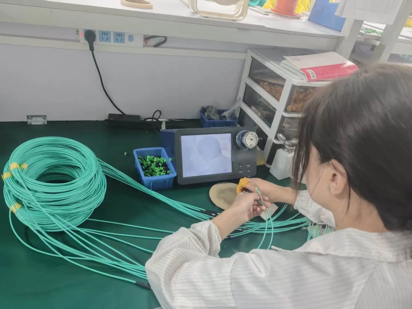
Technician checking an aqua patch cord end face with a video inspection scope at a workbench

For assemblies made in our own factory, the inspection and insertion-loss records go with the shipment; the values for your order are stated in the quotation and test report.

A Quote-Ready SR4 Cabling BOM

List cords and trunks as separate lines, and give polarity, gender and fiber count on each one. The lines below are an example of the format, not a real order.

Example SR4 cabling lines (Method B)
LineExample
CRD-01MPO-12 to MPO-12, Base-8, OM4, Type B, unpinned / pinned, 3 m, LSZH, qty per port count
TRK-01MPO-12 to MPO-12, Base-8, OM4, Type B, pinned / pinned, 35 m, label per port map
PNL-011U panel with key-up to key-up MPO adapters, ports per drawing
OpticsTransceiver part numbers at each end (to confirm connector gender)
TestsInsertion loss per assembly, polarity check, end-face inspection
CommercialQuantity, destination country, labels and packing

If an item is not decided, mark it "to be confirmed per project" rather than leaving it blank. Polarity and gender are the two fields buyers most often leave out, and they are the two that cannot be fixed on site without new parts.

Common SR4 Polarity Mistakes

  • Type A cord used for a direct link. Straight through: transmitters face transmitters.
  • Mixing methods. A Type B trunk with Type A cords on one end and Type B on the other produces an even mirror count.
  • Pinned cord into a pinned port. The connectors will not mate and forcing them damages the pins.
  • Flipping an adapter in the panel to "fix" polarity. It may work once, but the drawing no longer matches the panel and the next change fails.
  • Ordering by speed only. "100G MPO cable" does not say polarity type, gender, fiber grade or fiber count.

FAQ

SR4 MPO Polarity FAQ

Which MPO cable type do I need to connect two SR4 transceivers directly?

A Type B MPO-12 cord (key-up to key-up, position 1 to 12) with unpinned connectors at both ends, in the fiber grade your design uses, usually OM4.

Can I use a Type A MPO cord for 40G or 100G SR4?

Not on its own. A Type A cord connects position 1 to position 1, so transmit meets transmit. Type A cords are used in Method A only together with one Type B cord in the same channel.

Is Method B or Method A better for SR4?

For new multimode parallel links Method B is simpler because every cord is the same Type B part. Method A suits sites that already have Type A trunks. Use one method consistently across the installation.

Do SR4 cords need pins?

The cord end that plugs into the transceiver is usually unpinned, because transceiver ports are commonly pinned. Confirm the gender on the module data sheet.

Does 400G SR4.2 use the same MPO polarity as SR4?

It runs on the same 8-fiber MPO-12 cabling type as 40G and 100G SR4, so a correctly built SR4 plant usually supports it. Check the module data sheet for reach and loss limits.

Sources and Further Reading

Standards and public references describe definitions and industry practice; they are not Lumafyn product data. Optical values, MOQ and lead time for your order are confirmed in your quotation and test records.

Related products and guides

Get a Quote