
US fiber guide
Fiber Optic Loss Budget: Power Budget, Link Loss, and Margin
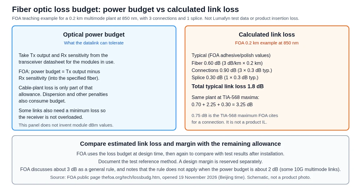
A fiber optic loss budget is an estimate of the end-to-end loss of a cable plant: fiber attenuation over length, plus connections, splices, and any other passive devices such as splitters. The optical power budget is different: it is the loss a transmitter-to-receiver datalink can tolerate. The Fiber Optic Association (FOA) defines that power budget as transmitter output minus receiver sensitivity, taken from the datasheet of the modules on the order. This article does not invent module power figures. The calculated plant loss has to fit inside the remaining allowance after penalties and a design margin.
Published 2026-11-20 · Last reviewed 2026-11-20 · By the Lumafyn Technical Team
Lumafyn products are made at an ISO 9001 / ISO 14001 / ISO 45001 certified production base (management-system certificates issued by NOA). The certificates cover the production base, not individual products.
View certificates →What is the difference between a power budget and a loss budget?
Worked figures in this guide are teaching examples from the FOA public loss-budget page, opened on 19 November 2026. They are not Lumafyn product insertion-loss values or factory test records. The two phrases answer different questions. On the FOA page “Calculating Fiber Optic Loss Budgets,” opened on 19 November 2026 at thefoa.org/tech/lossbudg.htm, the power budget is the amount of cable-plant loss a datalink can tolerate and still work properly. The FOA also writes it as the difference, in decibels, between transmitter output and receiver sensitivity, both referred to the fiber type specified for the link.
The loss budget — sometimes called an attenuation allowance — is the loss the cable plant should have if it is installed as designed. You calculate it by adding estimated component losses along the path. The FOA gives that estimate two jobs: at design time, to check that the cabling will work with the intended links; and after installation, to compare with measured insertion loss.
A datalink operates only if the actual plant loss sits inside the power budget. The FOA notes that a power budget can have both a minimum and a maximum: enough loss so the receiver is not overloaded, and not so much that it is starved of signal. Cable-plant loss is only part of the allowance. Distortion, including dispersion, also reduces it. This guide does not assign a penalty in decibels to a named transceiver, because no current module datasheet was opened for this draft.
What goes into a cable-plant loss budget?
Add the terms below, and write down every assumption: wavelength, fiber type, length, how many connections and splices you are counting, whether a splitter or other coupler is in the path, and which test method you will use later.
- Fiber loss. Multiply the attenuation you are using, in dB/km at the operating wavelength, by the length in kilometers. Use a value that matches the cable you are installing. The FOA warns against using the best possible fiber or connector specifications — leave yourself some margin.
- Connection loss. Count mated pairs, not loose connector bodies. The FOA is explicit that a connector by itself has no loss; only a connection has a loss in decibels. Include the connections at each end unless you already know the system specification excluded them.
- Splice loss. Add every fusion or mechanical splice in the path, including pigtail splices if they are part of the plant you are budgeting.
- Other passives. Add any coupler or splitter from its datasheet. The ideal split ratio is not the whole story; see the splitter section below.
- Document the test method. A one-cable 0 dB reference, the most common method when the test set matches the connectors, includes the end connections in the measured loss, so the budget should include them. A three-cable reference, often used for MPO plug-and-jack interfaces, already includes two connections in the reference; a budget written without the end connections will be closer to that result. Write the method next to the estimate.
If the design also uses equipment patch cords at each end, decide whether the budget and the later test include those cords. In the FOA example the connection count changes with that choice, and so does the total. The length, the count, and the method are design assumptions, not a record of a particular Lumafyn order.
How should you treat typical values, standard-maximum limits, and manufacturer limits?
These three kinds of number are not interchangeable. Mixing them is the usual way a spreadsheet looks “safe” on paper and then surprises you in the field.
| Item | What the FOA page states | How to use it |
|---|---|---|
| Typical adhesive/polish connection | 0.3 dB in the FOA example | Planning typical, not a promise for every pair |
| TIA-568 max acceptable connection | 0.75 dB; FOA says this is generally much too high except for array (MPO) connectors | Standard maximum cited by the FOA, not a Lumafyn product IL |
| Multimode splices | 0.1–0.5 dB; 0.3 dB is a good average; the example uses 0.3 dB | Planning typical for that example |
| Single-mode fusion splices | Typically less than 0.05 dB | Typical fusion result, not a mechanical splice |
| Fiber attenuation in the FOA 0.2 km example | Typical [TIA max]: MM 3 [3.5] dB/km at 850 nm, 1 [1.5] at 1,300 nm; SM 0.4 [1/0.5] at 1,310 nm, 0.3 [1/0.5] at 1,550 nm. Higher SM loss is allowed in premises | Teaching values, not jumper IL or a transceiver spec |
The same FOA page also gives typical multimode connections of 0.2–0.5 dB, factory-made fusion-spliced single-mode connections of 0.1–0.2 dB, field-terminated single-mode connections that may be 0.5–1.0 dB with unacceptable reflectance (not recommended), and an EIA/TIA 568 splice maximum of 0.3 dB as stated by the FOA. A manufacturer limit is different again: it is the value published for a specific part, or the value on the test record for a finished assembly. If the channel uses our patch cords or trunks, use the quotation and the test records — not the 0.75 dB standard maximum or the FOA typical 0.3 dB as if either were a Lumafyn product rating.
The FOA calculates its short example at both typical and TIA worst-case values. It suggests the typical column is often reasonable for adhesive/polish or fusion splice-on connectors, while MPO or pre-polished mechanical-splice connectors may fit the TIA column better. That is a teaching discussion, not a pass/fail rule for a Lumafyn product line.
What does a worked teaching example look like?
The figures in this section are a teaching example copied from the FOA’s 0.2 km multimode cable-plant example. They are not a Lumafyn laboratory test and not a specification for a sellable product. The plant in the example is 200 m (0.2 km) long, counted without the equipment patch cords, so the FOA includes three connections and one splice.
| Contribution at 850 nm | Typical column (dB) | TIA-568 maximum column (dB) |
|---|---|---|
| Fiber (0.2 km) | 0.6 (from 3 dB/km) | 0.7 (from 3.5 dB/km) |
| Connections (3) | 0.9 (3 × 0.3) | 2.25 (3 × 0.75) |
| Splice (1) | 0.3 | 0.3 |
| Other | 0 | 0 |
| Total link loss | 1.8 | 3.25 |
At 1,300 nm the same FOA table gives a typical total of 1.4 dB and a TIA-maximum total of 2.85 dB, because the fiber term falls to 0.2 dB typical (0.3 dB maximum) while the connection and splice terms stay the same in that example.
You can use the same addition on a longer plant if you change the length, wavelength, fiber attenuation, and connection and splice counts, and you label the result as your estimate. Do not drop a standard-maximum connection loss of 0.75 dB into a product cell, and do not treat the 1.8 dB or 3.25 dB totals as a factory result.
Where do splitters fit in a loss budget?
If a splitter sits in the plant, its insertion loss belongs in the “other passives” line. For a uniform 1×N device, the theoretical split is a teaching formula: 10 × log10(N) dB. That is about 3.01 dB for 1×2, 6.02 dB for 1×4, 9.03 dB for 1×8, 12.04 dB for 1×16, and 15.05 dB for 1×32.
A real splitter also has excess loss, and the ports are not perfectly equal. Those values come from the splitter datasheet or from a labeled planning table, not from this formula alone. Uniform 1×2 through 1×64 planning figures already live on the PLC splitter ratio selection guide. This article does not reprint that table or take over that page’s keyword. Uneven (unbalanced) splitters are not recalculated here.
How should you treat design margin?
Margin is a reserved allowance, not a measured component. The FOA makes two related planning comments, not a Lumafyn rule. When you move from the electronics’ dynamic range (transmitter output minus receiver sensitivity) to the loss the cable plant is allowed, it says to subtract some margin for degradation over time or environment — “as much as 3 dB.” After a teaching power-margin table, it also writes that, as a general rule, the remaining link-loss margin should be greater than approximately 3 dB, because sources age, connections can degrade or get dirty, and restoration splices after a cut need headroom.
The same paragraph limits that rule of thumb: “The 3 dB rule, of course, is irrelevant if the power budget is ~2 dB like some of the 10G multimode links.” This article does not turn “3 dB” into a required Lumafyn margin, and it does not invent a power budget for a 10G or 100G module. Take transmitter and receiver figures from the datasheet of the modules on the order, apply any published penalties, and write down the margin you actually reserve.
An IEEE 802.3 operating range also does not replace this calculation. It is a standardized distance for a named PMD and fiber type, already summarized for multimode jumpers in the OM3 vs OM4 patch cord guide. Those distances are not a calculated plant loss, not a transceiver output or sensitivity, and not the insertion loss of a finished patch cord or trunk.
How do you compare the estimate with tests, and what belongs on an RFQ?
After installation, the FOA uses the same loss budget as a reference for measured insertion loss. Because the calculated budget is an estimate, and measurements have uncertainty, it cautions that results close to the estimate need judgment: you should not automatically fail a good fiber or pass a bad one just because a reading sits near the line. Use the same wavelength, the same plant extent (with or without equipment patch cords), and the same 0 dB reference method you wrote down when you built the budget.
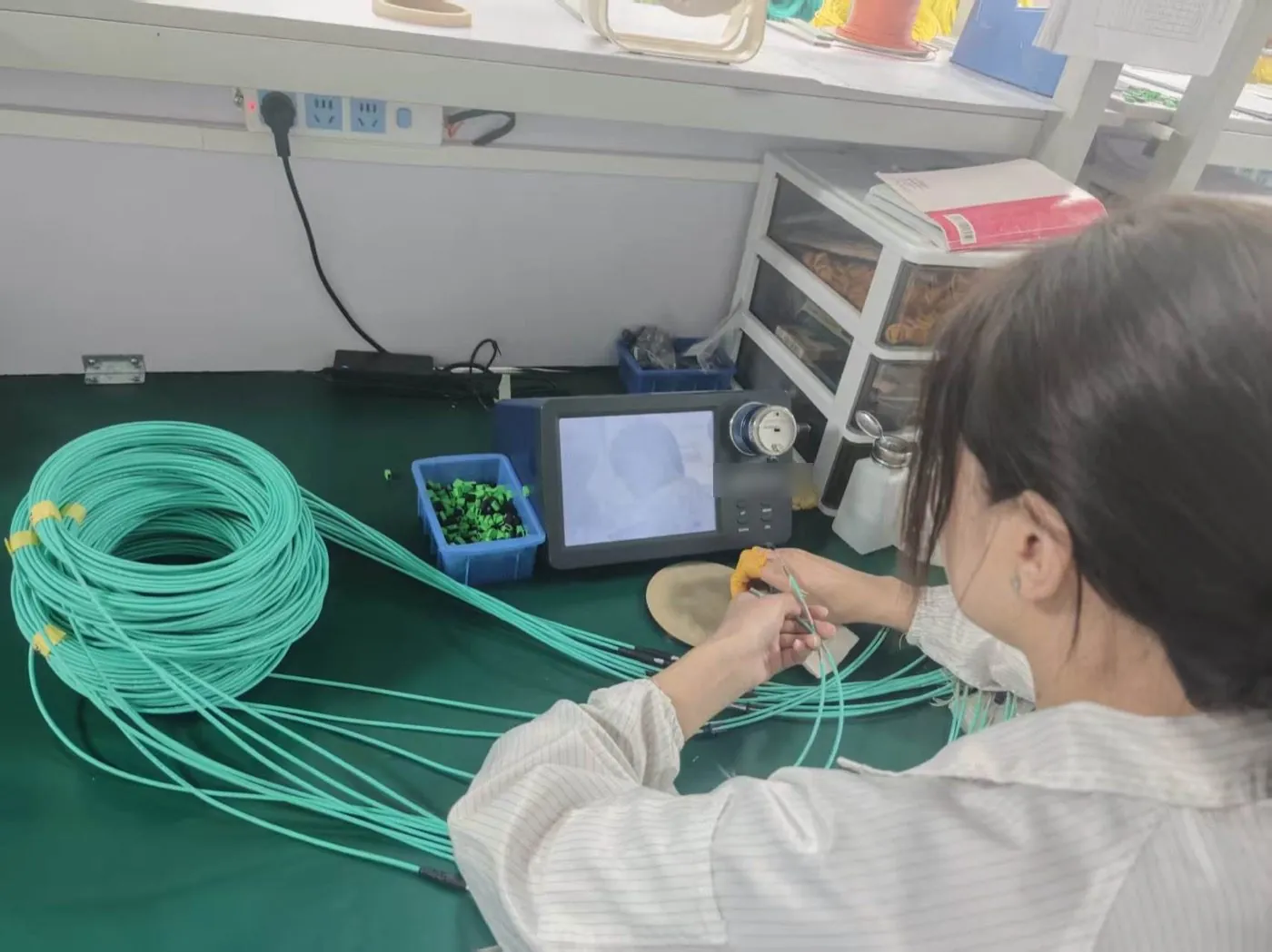
A patch-cord test record confirms the finished jumper in your hand. Compare a channel or permanent-link test, done with a documented reference method, with the plant budget. Read a single-cord report with the patch cord test report guide. Keep the two documents distinct.
On an RFQ, include fiber type and grade, wavelength, and length; connectors and whether equipment patch cords are in the budget; connection and splice counts, including pigtail splices if they are in the plant (see the fiber pigtail vs patch cord guide); any splitter port and its datasheet loss, not only the ideal 10 × log10(N) term; the handover test method; and a request that the module datasheet — not this article — supply transmitter and receiver figures.
Standard jumpers are listed on the fiber optic patch cord wholesale page, trunks on the MPO/MTP trunk cable page, and US delivery context on the United States fiber optic supplier page. None of those pages turns the FOA teaching totals into a product rating. This article does not add product certifications, a minimum order, a lead time, or a supply commitment. Optical values for an order are confirmed on the quotation and the test records.
FAQ
Fiber optic loss budget FAQs
Is a fiber optic loss budget the same as an optical power budget?
No. The FOA treats the power budget as the loss a transmitter-to-receiver datalink can tolerate, taken from transmitter output minus receiver sensitivity. The loss budget is the estimated end-to-end loss of the cable plant. The plant has to fit inside the remaining power-budget allowance after penalties and margin.
Can I use the 0.75 dB TIA-568 maximum as my patch-cord insertion loss?
No. On the FOA page, 0.75 dB is the TIA-568 maximum acceptable connection loss used in a worst-case teaching column. The FOA itself calls that ceiling generally much too high except for array (MPO) connectors. It is not a Lumafyn product insertion-loss value. Use the quotation and the test records for the assemblies on the order.
Do I have to include the connectors on each end?
Usually yes, unless you already know the system specification excluded them. The FOA’s starting position is to include the end connections. A one-cable reference typically includes those connections in the measured loss; a three-cable reference, often used for MPO, does not line up with a budget that still adds the two end connections. Write the method down with the estimate.
What margin should I reserve?
This article does not invent a required margin. The FOA discusses subtracting as much as 3 dB for aging and environment, and it treats a remaining margin of about 3 dB as a general rule, while also stating that the 3 dB rule is irrelevant when the power budget is about 2 dB, as on some 10G multimode links. Take transmitter and receiver numbers from the module datasheet, and record the margin you actually set aside.
Does a 1×N splitter add only 10 × log10(N) dB?
That formula is the ideal uniform split, shown here as a teaching calculation. A real device also has excess loss and port-to-port variation, which you take from the splitter datasheet or from a labeled planning table. Uniform PLC ratio planning already has its own guide; this page does not reprint that table.
Can an IEEE reach table replace this calculation?
No. Standardized reach is an operating distance for a named PMD and fiber type. It is a useful check when you choose a grade, but it is not a substitute for adding fiber, connections, splices, any splitter, and margin on the plant you are installing.
Sources and Further Reading
Standards and public references describe definitions and industry practice; they are not Lumafyn product data. Optical values, MOQ and lead time for your order are confirmed in your quotation and test records.