
FTTH / ISP planning
Unbalanced Fiber Splitter: When Unequal Taps Fit an FTTH or ISP Line
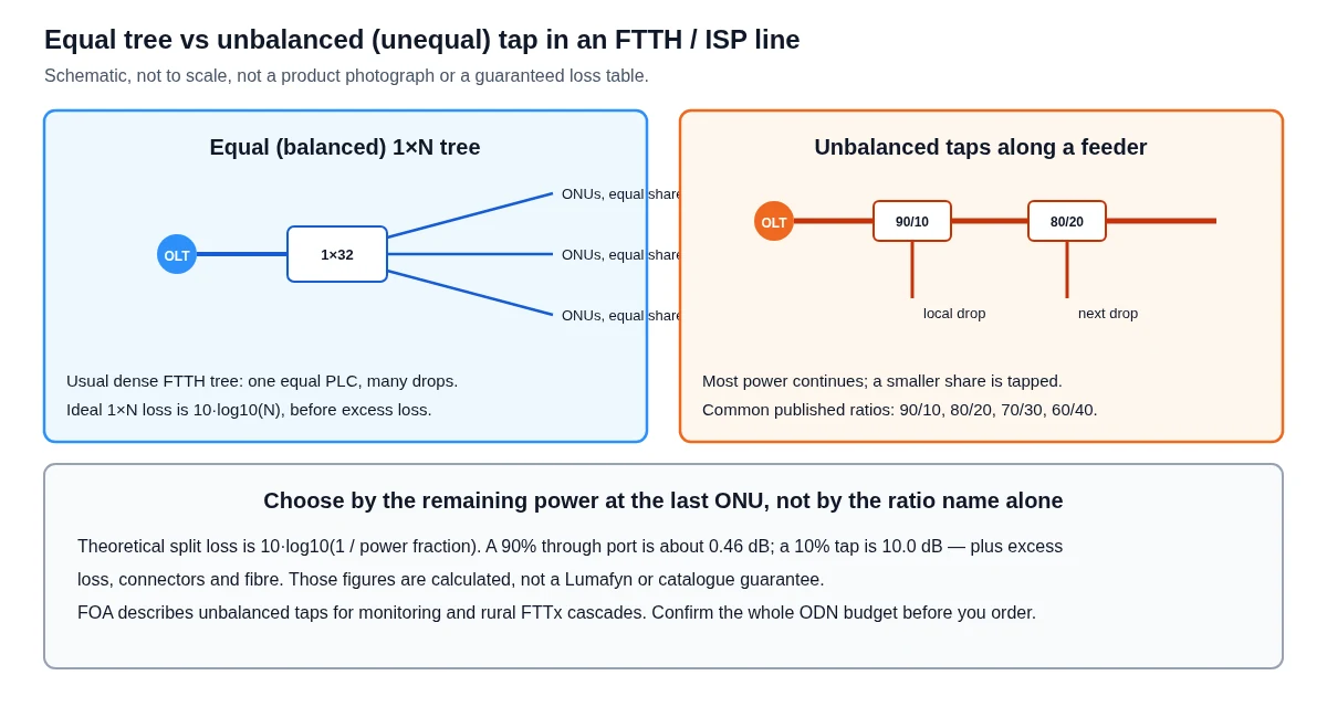
An unbalanced fiber splitter, also called an unequal splitter or optical tap, divides power unevenly: most of the light continues along a through port and a smaller share is taken off for a local drop or a monitor. The Fiber Optic Association’s public note on optical splitters, opened on 18 November 2026, lists common asymmetrical ratios as 90/10, 80/20, 70/30 and 60/40, and places them in monitoring use and in rural FTTx cascades. An equal 1×32 tree still suits a dense PON. This guide is about when the unequal tap is the better planning tool, not a repeat of an FBT-versus-PLC technology comparison or a 1×2-to-1×64 equal-loss table.
Published 2026-11-19 · Last reviewed 2026-11-19 · By the Lumafyn Technical Team
Lumafyn products are made at an ISO 9001 / ISO 14001 / ISO 45001 certified production base (management-system certificates issued by NOA). The certificates cover the production base, not individual products.
View certificates →What is an unbalanced or unequal fiber splitter?
In an equal, or balanced, splitter the input is divided as evenly as the device allows among N outputs. In an unbalanced, or unequal, splitter the ports are intentionally different. A 90/10 tap is meant to keep about 90% of the optical power on the through path and deliver about 10% to the tap port, before excess loss and connectors.
The FOA page Optical splitter groups devices this way: asymmetrical splitters or taps, most often 90/10, 80/20, 70/30 and 60/40, used to tap a system for monitoring or to build FTTx PON networks in rural areas; and symmetrical splitters, used most often in FTTH PON trees such as 1:2, 1:8, 1:16, 1:32 and 1:64. That is a planning classification, not a brand list.
The same idea appears under several catalogue names — unequal coupler, tap coupler, unbalanced PLC, asymmetric splitter. The useful question for an ISP planner is not the name. It is how much power remains at the last ONU after every through port, every tap, every connector and the fibre itself.
How is the theoretical split loss calculated?
For an ideal divider, split loss in decibels is 10 × log10(1 / power fraction). The FOA note writes the equal-splitter form as 10 × log10(1 / N). The same logarithm applied to a 90/10 or 70/30 fraction gives the theoretical split only. Real devices add excess loss, uniformity, wavelength dependence and, if they are connectorised, connector loss.
| Named ratio (through / tap) | Through fraction | Theoretical through loss (dB) | Theoretical tap loss (dB) |
|---|---|---|---|
| 50/50 | 0.50 | 3.01 | 3.01 |
| 60/40 | 0.60 | 2.22 | 3.98 |
| 70/30 | 0.70 | 1.55 | 5.23 |
| 80/20 | 0.80 | 0.97 | 6.99 |
| 90/10 | 0.90 | 0.46 | 10.00 |
| 95/5 | 0.95 | 0.22 | 13.01 |
Those decibel values were calculated for this guide from 10 × log10(1 / fraction), rounded to two decimal places. They are not ITU-T limits, not FOA “typical” figures, and not Lumafyn insertion-loss data. A real 90/10 device will be worse than 0.46 dB / 10.0 dB once excess loss is included. Always add the supplier’s stated excess or maximum insertion loss, then the rest of the ODN, before you decide that a cascade will close.
ITU-T G.671 is the recommendation that defines parameters for optical branching components, such as insertion loss and uniformity. This article does not reproduce a manufacturer’s limit table from that recommendation. Equal-ratio PLC loss for 1×2 through 1×64 is already tabulated, for planning, in our PLC splitter ratio selection guide. That table is not repeated here.
When does an ISP or FTTH planner use a tap instead of an equal tree?
Use an equal 1×N tree when a compact, high-count group of subscribers can share one splitter location and the same budget on every drop. That is the usual dense GPON layout: one PLC, many equal ports, short drops.
Use a string of unbalanced taps when subscribers sit along a long feeder and you do not want to run a high-count distribution cable back from a single 1×32. The FOA note describes cascade connections in suburban and rural FTTx, and in some building risers: the first device can be a symmetrical splitter or a tap, and later devices may be symmetrical splitters feeding local drops. It also warns that more than two splitting levels can make maintenance and OTDR work harder, especially when splitters sit close together.
A monitor tap is a different use of the same device type. A 90/10 or 95/5 coupler can take a small share of the signal for a test point without creating a full subscriber split. That tap still consumes budget and must be written into the calculation.
The last ONU on a tap chain sees every through-port loss plus its own tap, fibre and connectors. If you place a 70/30 too early, the through path may be starved before the end of the road. If you place a 90/10 on a short, high-count spur, the tap port may be too weak after a further equal split. The ratio has to change along the line, which is why a single “standard 70/30” line is rarely enough for a whole village.
How is this different from FBT vs PLC, or from a PLC ratio table?
Technology and ratio are two different decisions. Whether the device is made as a fused coupler or as a planar chip is covered in the already published FBT vs PLC splitter guide. That article left unequal taps for this follow-up, and it should stay the place for wavelength flatness, low port-count couplers and equal high-count PLC trees.
The PLC ratio guide answers “1×8, 1×16, 1×32 or 1×64?” for an equal tree and gives a loss table for those counts. This page answers “when should the ports be unequal, and how do I think about 90/10 versus 70/30?” It does not replace either of those guides, and it does not try to rank FBT against PLC again.
Unbalanced devices can be built either way. A low-count 90/10 is often a fused coupler in published lists; some planar devices are also offered with unequal ratios. Choose the ratio from the remaining budget first, then the package and the technology from the environment and the wavelength plan. Do not assume that “unbalanced” on an RFQ automatically means one process.
What should you write on an ODN specification?
Write the ratio in the through/tap order you intend, the wavelengths, the package, whether the ports are connectorised, and the budget you used — including fibre, splices and connectors, not only the theoretical split.
| Line | Example wording |
|---|---|
| Device | 1×2 unbalanced splitter, 90/10 (through / tap), single-mode, wavelengths covering the PON plan you actually use |
| Cascade | Through port onward to the next tap; tap port into a local 1×4 or 1×8 equal splitter, as the drawing |
| Budget | List theoretical split, stated excess or maximum insertion loss, connector count, fibre length and the OLT/ONU budget class you are designing to |
| Package | Bare fibre, ABS box, cassette or rack, indoor or outdoor housing as the closure allows |
| What not to write | Only “unbalanced splitter” with no ratio, no through/tap orientation and no remaining-power check at the last ONU |
Confirmed PLC products are quoted from the PLC splitter supplier page. This guide does not add a new product family, a minimum order or a lead time, and it does not claim every unequal ratio as stock. If a ratio or package is not in the quotation, it is not confirmed. Southeast Asia delivery context sits on the Southeast Asia fiber optic supplier page.
Optical values for a specific order are confirmed on the quotation and the test records. Connector types that are not a confirmed Lumafyn supply item are named here only where a public source uses them as examples; they are not a stock list.
What mistakes should you avoid with unequal splitters?
- Using a ratio name as if it were a finished loss figure. 90/10 is a target fraction; theoretical through loss is about 0.46 dB, and the installed loss is higher.
- Repeating the same tap ratio all the way down a long feeder without checking the last ONU.
- Cascading many levels without a maintenance and OTDR plan. The FOA note cautions against more than two splitting levels where it can be avoided.
- Treating this page as a new 1×2-to-1×64 equal-loss chart, or as a second FBT vs PLC essay. Those jobs belong to the two existing guides linked above.
- Ordering an unequal device “for GPON” without writing the through and tap orientations on the drawing, so the high-loss port is accidentally placed in the through path.
FAQ
Unbalanced Fiber Splitter FAQ
What is an unbalanced or unequal fiber splitter?
It is a splitter or coupler whose ports are not meant to be equal. Common published tap ratios are 90/10, 80/20, 70/30 and 60/40. Most of the power stays on the through port; a smaller share is taken off for a drop or a monitor.
How much loss does a 90/10 or 70/30 splitter have?
The theoretical split alone is about 0.46 dB through and 10.0 dB on the tap for 90/10, and about 1.55 dB / 5.23 dB for 70/30, from 10 × log10(1 / fraction). Real insertion loss is higher once excess loss and connectors are included. Use the supplier’s stated limits and a full ODN budget, not this theoretical table, as the design number.
When should an ISP use unequal taps instead of a 1×32 PLC?
When subscribers sit along a feeder and a single equal tree would need a high-count cable back from one point, or when you only need a small monitor tap. Dense clusters still usually use an equal PLC tree. Check remaining power at the last ONU.
Is an unbalanced splitter the same as FBT or PLC?
No. Unbalanced describes the ratio. FBT and PLC describe how the device is made. Either process can be used for some unequal ratios. See the FBT vs PLC guide for the technology choice.
Can I cascade several 90/10 taps on one PON port?
Sometimes, in a rural or linear layout, but each through port consumes budget and extra levels make testing harder. The FOA note recommends keeping the number of splitting levels to one or two where you can, and you must still close the optical budget for the last ONU.
Are the ratios in this article Lumafyn stock items?
No. The ratios are planning examples from public practice and from calculated split loss. Only ratios and packages confirmed on a quotation are offered. Test records apply to the finished items on that order.
Sources and Further Reading
- FOA, Optical splitter (opened 18 November 2026): balanced vs asymmetrical taps, common 90/10 to 60/40 ratios, rural cascade notes, ideal 10·log10(1/N) form)
- Lumafyn: FBT vs PLC splitter (technology choice; unequal taps left to this follow-up)
- Lumafyn: PLC splitter ratio selection guide (equal 1×2–1×64 planning table, not repeated here)
Standards and public references describe definitions and industry practice; they are not Lumafyn product data. Optical values, MOQ and lead time for your order are confirmed in your quotation and test records.