
FTTH splitters
FBT vs PLC Splitter: Which to Use in FTTH and ISP Networks
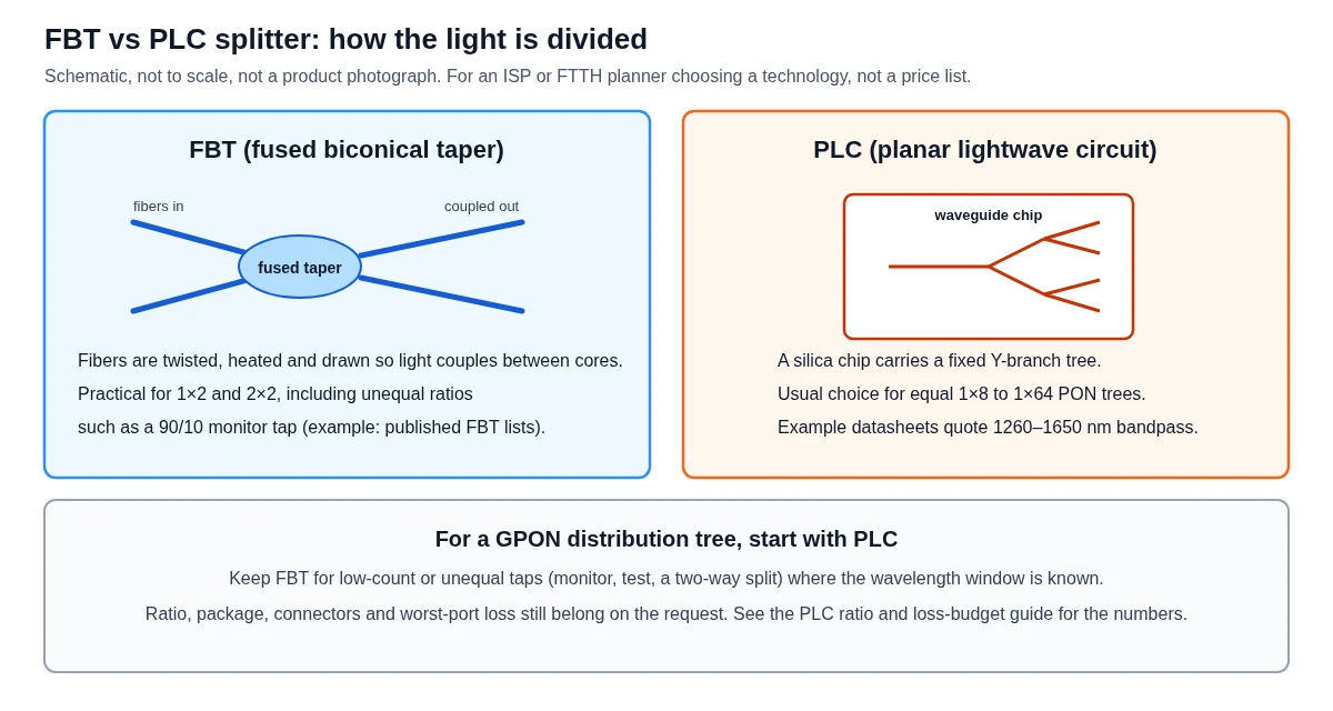
An FBT vs PLC splitter decision is about how the light is divided, and how evenly every subscriber port will behave on a PON tree. An FBT (fused biconical taper) device is made by twisting, heating and drawing fibers so power couples between cores. A PLC (planar lightwave circuit) splitter uses a waveguide tree on a silica chip. For a typical equal 1×8, 1×16 or 1×32 GPON tree, a PLC splitter is the practical starting point; keep FBT for low-count or unequal taps. Ratio and loss-budget tables stay in the PLC splitter ratio guide.
Published 2026-11-18 · Last reviewed 2026-11-18 · By the Lumafyn Technical Team
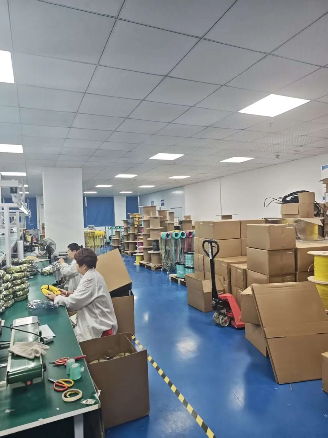
Lumafyn products are made at an ISO 9001 / ISO 14001 / ISO 45001 certified production base (management-system certificates issued by NOA). The certificates cover the production base, not individual products.
View certificates →What is the difference between an FBT and a PLC splitter?
The difference between an FBT and a PLC splitter is the manufacturing method, which then shows up as wavelength behaviour, practical split count, and whether unequal ratios are easy to make.
| Point | FBT (fused biconical taper) | PLC (planar lightwave circuit) |
|---|---|---|
| How it is made | Fibers are twisted, fused under heat and drawn into a taper so light couples between cores | A waveguide tree is formed on a silica chip; the split is set by the chip layout |
| Typical job on an ISP network | Low-count splits and unequal taps (monitor, test, a two-way split) | Equal distribution on a PON tree, commonly 1×8 to 1×64 |
| Wavelength behaviour | Often built and tested around chosen windows; response can change away from those windows | Public example datasheets quote a wide, flat band, commonly 1260–1650 nm |
| Unequal ratios | Common on published 1×2 FBT lists (for example 90/10 or 70/30) | Equal 1×N and 2×N trees are the usual PLC offering |
| What this table is not | A set of Lumafyn insertion-loss or price figures | A set of Lumafyn insertion-loss or price figures |
The theoretical split loss of an ideal, equal 1×N device is 10 × log10(N) dB — about 3 dB for 1×2, 9 dB for 1×8, 15 dB for 1×32. Real devices add excess loss, and the port-to-port spread (uniformity) matters as much as the average, because the worst port is the one that decides whether the farthest customer still has margin. Those budget arithmetic details, including an example 1×32 working, are already in the PLC ratio guide and are not repeated as a second loss chart here.
ITU-T G.671 is the recommendation that covers transmission characteristics of optical components and subsystems, including branching components. ITU-T G.984.2 sets the GPON physical-media power-budget classes that the splitter has to fit inside. Quote the standard the operator uses, then ask the supplier for worst-port loss on the finished, packaged part — not a typical chip-only number.
When should an FTTH or ISP build use a PLC splitter?
Use a PLC splitter when you need an equal, multi-port distribution tree that must stay usable across the wavelengths a PON actually carries.
A GPON tree carries downstream and upstream traffic in different windows on the same fiber. ITU-T G.984.2 defines the GPON PMD and the optical power-budget classes (for example Class B+ and Class C+ in operator practice). Later PON generations add further downstream wavelengths on plant that often keeps the same splitters in the field. A device whose loss stays useful across a wide band is the usual choice for that tree, which is why public PLC datasheets so often quote a 1260–1650 nm bandpass. One example is CommScope’s published bare PLC specification, which lists 1260–1650 nm and equal 1×N configurations; those figures are CommScope’s published maxima, not Lumafyn product data.
Equal 1×16 and 1×32 splits are the everyday ISP case in a single-stage ODN. Building the same counts by cascading several FBT 1×2 stages stacks the excess loss and the uniformity of every stage, so the worst output port — not the average port — decides whether the last customer stays inside the budget. For that job, a single PLC tree is the practical technology. The existing ratio guide is the place to check whether a 1×32, or a cascade such as 1×4 plus 1×8, fits the route.
PLC devices are sold in several packages (bare fiber, mini tube, ABS box, LGX, rack). Package is a placement choice — cabinet, joint closure, or frame — and does not change the FBT-versus-PLC technology decision. Names such as FAT, ODP or ODC describe boxes in some national FTTH designs; this article does not claim supply of those housings.
When is an FBT coupler still the better choice?
An FBT coupler is still the better choice when you need a low port count or an unequal ratio, and you know the wavelength window it will live in.
Published FBT lists commonly offer 1×2 and 2×2 devices, including asymmetric ratios such as 90/10, 80/20 or 70/30. CommScope’s published FBT coupler table is one public example of that range, including a 50/50 coupler and a set of unequal taps. An ISP can use a small unequal FBT as a monitor or test tap on a feed, or as a two-way split, without buying a 32-port chip.
FBT is also how many older plants built low-count splits at a lower piece price. That history does not make a cascaded FBT 1×32 the right default for a new GPON tree. If a legacy design already uses FBT taps on a single-wavelength segment, leave those taps where they are specified, and specify PLC on the multi-wavelength distribution tree unless the operator standard says otherwise.
A full treatment of unbalanced / unequal fiber splitters in ring or linear FTTH is in the follow-on guide. This page only records that unequal ratios are a natural FBT job, and that they should be written as explicit percentages on the request, with loss quoted on both the through port and the tap port.
How do wavelength and uniformity affect a PON tree?
Wavelength and uniformity matter because a PON tree is shared, and the customer on the worst port still has to meet the same power-budget class as everyone else.
If a coupler is tuned near 1310 nm or 1550 nm and rolls off elsewhere, one service on the tree can pass while another — a video overlay, or a later downstream wavelength — sits closer to the margin. PLC waveguides, being geometric, are the reason many operators standardise on a wide-band PLC for the distribution split and leave narrow-window FBT devices for jobs that stay in a known band.
Uniformity is the spread between the best and worst output ports. On a 1×32, a uniformity figure of a little over a decibel is the difference between a comfortable last drop and a complaint from one street. Ask for the maximum insertion loss on the worst port of the packaged, connectorised part you will install, at the wavelengths the plant uses. Do not design from an unpublished typical value, and do not treat a chip-only figure as the installed loss if the part will be delivered with connectors and a box.
FOA’s public FTTH/PON note is a clear description of why splitters sit in the loss budget at all. Combine that with the operator’s G.984.2 class and the route lengths you actually have, using the worked example in the ratio guide rather than inventing a second budget table here.
What should you put on a splitter request?
Write the technology, the ratio, the package, the connectors, the lead lengths, and the worst-port loss you will accept, then say which wavelengths the device must meet.
| Field | What to write |
|---|---|
| Technology | PLC for an equal PON tree; FBT for a 1×2 or an unequal monitor tap |
| Ratio | 1×32 equal, or 1×2 at 90/10, stated as such |
| Package and leads | ABS box or mini tube; input and output lead lengths |
| Connectors | SC/APC is common on GPON plant; write the polish you actually use |
| Optical requirement | Maximum insertion loss on the worst port, at the plant wavelengths; uniformity if the operator specifies it |
| Standards hook | The ITU-T budget class or operator specification the tree must meet |
Finished PLC devices for quotation are listed on the PLC splitters page. The PLC splitter ratio selection guide remains the page for ratio and loss-budget arithmetic, including the 1×2 to 1×64 table already published there. Materials around a 1:32 ODN are listed in the GPON ODN materials list. Regional context for buyers in the Philippines, Malaysia, Singapore and neighbouring markets is on the Southeast Asia fiber optic supplier page.
Optical values, packing and any date or quantity limits are confirmed on the quotation and the test records for that order. This article does not add certifications, a minimum order, a lead time, or trade documents such as Form E.
FAQ
FBT vs PLC Splitter FAQ
What is the main difference between an FBT and a PLC splitter?
FBT devices are made by fusing and drawing fibers so that light couples between cores. PLC splitters use a waveguide tree on a silica chip. The methods lead to different practical split counts, wavelength behaviour and ease of making unequal ratios.
Should a new GPON 1×32 tree use FBT or PLC?
A PLC splitter is the practical choice for an equal 1×16 or 1×32 distribution tree that must carry more than one PON wavelength. Cascading FBT 1×2 stages to reach 1×32 stacks excess loss and uniformity on the worst port.
When is an FBT coupler still useful?
Use FBT for low-count splits and unequal taps, such as a 90/10 monitor or a simple 1×2, when the wavelength window is known. Published FBT lists commonly include those asymmetric ratios.
Where are the 1×2 to 1×64 loss figures on this site?
They stay in the PLC splitter ratio selection guide, which already includes a loss table and a 1×32 budget example. This page does not republish that chart or invent a second set of numbers.
Does this page offer FAT or ODP housings?
No. FAT, ODP and similar names are used in some national FTTH designs for boxes. They are mentioned only as placement context. Supply of those housings is not claimed here.
Sources and Further Reading
- ITU-T G.671: transmission characteristics of optical components and subsystems
- ITU-T G.984.2: GPON physical media dependent layer (power-budget classes)
- FOA: FTTH / PON design and the role of splitters
- CommScope Bare Splitter & Coupler Specification Guide (example published PLC 1260–1650 nm bandpass and FBT unequal-ratio list)
- Lumafyn PLC splitter ratio selection guide (loss table and budget example already on this site)
Standards and public references describe definitions and industry practice; they are not Lumafyn product data. Optical values, MOQ and lead time for your order are confirmed in your quotation and test records.