MTP/MPO Assemblies · Built to Order

MPO to LC Breakout Cable Manufacturer for Custom Fan-Out Assemblies

An MPO to LC breakout cable has one MPO/MTP connector on one end and separate LC connectors on the other, so a single array port or trunk can feed several duplex devices without a cassette. As an MPO to LC breakout cable manufacturer, Lumafyn builds each fan-out to your drawing in our own factory: fiber count, fiber type, MPO gender and polish, polarity, LC polish, leg type, leg lengths and labels. Optical values, MOQ and lead time are confirmed in your quotation before production.

Last reviewed 2026-11-13 by the Lumafyn Technical Team · Orders are produced in our own factory in China.

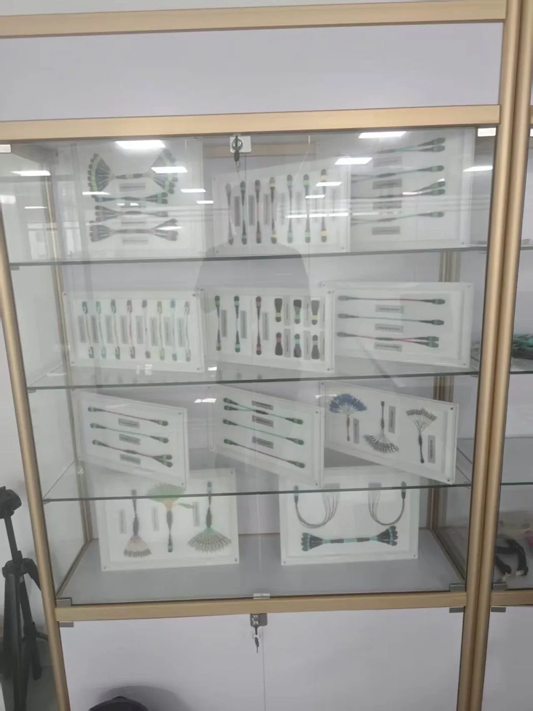
Glass display cabinet with framed MPO fan-out and fiber cable assembly samples
ISO 9001:2015ISO 14001:2015ISO 45001:2018

Lumafyn products are made at an ISO 9001 / ISO 14001 / ISO 45001 certified production base (management-system certificates issued by NOA). The certificates cover the production base, not this cable as a product.

View certificates →

What an MPO to LC Breakout Cable Does

An MPO to LC breakout cable converts one multi-fiber MPO interface into individual LC channels inside the cable itself. The Fiber Optic Association describes MPO cables as coming in two forms: MPO on both ends for backbones, or breakout cables with an MPO on one end and single fiber connectors on the other. This page covers the second kind with LC ends.

Buyers usually order breakouts for three jobs:

  • Parallel optic to duplex ports. A switch port with a parallel optic is split to several duplex LC ports on servers, storage or another switch.
  • Trunk to equipment without a cassette. The breakout plugs into an MPO adapter in front of a trunk and the LC legs go straight to the equipment.
  • Testing and fault finding. The FOA recommends adding breakout cables to both MPO ends when testing an MPO cable plant with a single-fiber source and power meter.

Names vary between suppliers: breakout, fan-out, branch harness and hydra cable are often used for the same build. To avoid a wrong quote, describe what each end plugs into rather than relying on the name.
Common MPO to LC Breakout Configurations

The fiber count of the MPO end decides how many LC legs a breakout has, and parallel optics often leave some MPO positions unused. The FOA notes that MPO ferrules carry rows of 12 or 16 fibers, and that 12 or 24 fibers are the versions with the widest market acceptance. Its data center page shows multimode 40G parallel links using 8 fibers: 4 transmit, 4 receive and 4 unused.

MPO to LC breakout configurations and what to confirm (fiber counts per FOA references; not Lumafyn product limits)
BuildFibers usedLC legsTypical useConfirm on the RFQ
MPO-8 (Base-8) to LC duplex84 duplexParallel optic split to four duplex portsWhich MPO positions carry signals; the optic's lane map
MPO-12 to LC duplex, 8 fibers used8 of 124 duplexSame split on a 12-position connectorUnused positions stated, not assumed
MPO-12 to LC duplex126 duplexTrunk to equipment in Base-12 designsPolarity method of the trunk
MPO-24 to LC duplex2412 duplexHigher-density trunk to equipmentRow and position order for all 24 fibers

Check fiber count against the transceiver data sheet and the trunk, not just the connector size. Lane assignments and reach belong to the specific optic. For parallel-optic channels, our SR4 MPO polarity guide walks through the common cases.

Singlemode or Multimode: Polish on Each End

Specify the polish separately for the MPO end and the LC ends, because they are often different. According to the FOA, multimode MPO connectors generally have flat ferrules, while singlemode MPOs have angled ferrules at the same 8 degree angle used on single-fiber APC connectors. The FOA also notes there appears to be no standard on the orientation of the angled surface, toward or away from the key, so check it against the mating trunk or panel.

On the LC side, most duplex transceivers expect UPC. AddOn Networks advises using UPC connectors unless the transceiver states APC is accepted. If the LC legs land in an APC patch field instead, order LC/APC. TIA-568 colour coding helps on site: the FOA lists blue for singlemode and green for singlemode APC connector bodies or boots. For the full comparison, read APC vs UPC connectors.

Polarity and MPO Gender

A breakout cable must continue the polarity and gender of whatever it mates with, so transmit fibers land on receive ports at the far end. The FOA states that when two MPOs are mated, one connector must have pins and another holes. A breakout that plugs straight into a transceiver takes the opposite gender to the transceiver port, and one that mates to a trunk through an adapter takes the opposite gender to the trunk end. Check the module data sheet and the trunk drawing before you choose.

For polarity, name the method used in the rest of the channel (Type A, B or C trunks with matching cords, or a project-specific map). Our MTP/MPO polarity guide explains the methods; on the RFQ, a simple table of MPO position to LC leg label is the most reliable instruction.

Leg Length, Stagger and Labels

Leg design decides how tidy the installation is, so give leg lengths as a drawing or a table rather than one number. Equal legs suit a single device. Staggered legs suit a row of ports, with each leg slightly longer than the one before so slack does not pile up at the first port. There is no public standard step for stagger, so write the port pitch, the shortest and longest leg, or attach the drawing.

  • Overall length: measured from the MPO end to the breakout point, or to the leg tips. Say which.
  • Leg type: individually jacketed legs for routing through managers; bare fan-out legs only for protected spaces such as inside an enclosure.
  • Breakout point: position of the furcation and whether a pulling grip is needed for the MPO end.
  • Labels: leg numbers that match your port map, plus an end label at the MPO.

When a Breakout Cable Is the Right Choice

A breakout cable is the right choice when the port map is fixed and you want the shortest path from an MPO port to duplex equipment. A cassette is the better choice when you need a labeled patch field for frequent moves. Every extra mated pair counts against the loss budget: the FOA's loss budget example uses 0.75 dB per connection as the TIA-568 maximum acceptable, and its data center page points out that this limit allows only two connections in a short high-speed link. These are standards allowances, not Lumafyn product values.

A trunk-plus-cassette-plus-patch-cord path adds connections that a direct breakout avoids. Our MPO breakout vs harness vs cassette guide compares the three in detail. If the backbone is part of the order, see MPO/MTP trunk cables and MPO cassettes and high-density panels.

How We Build and Check Breakout Assemblies

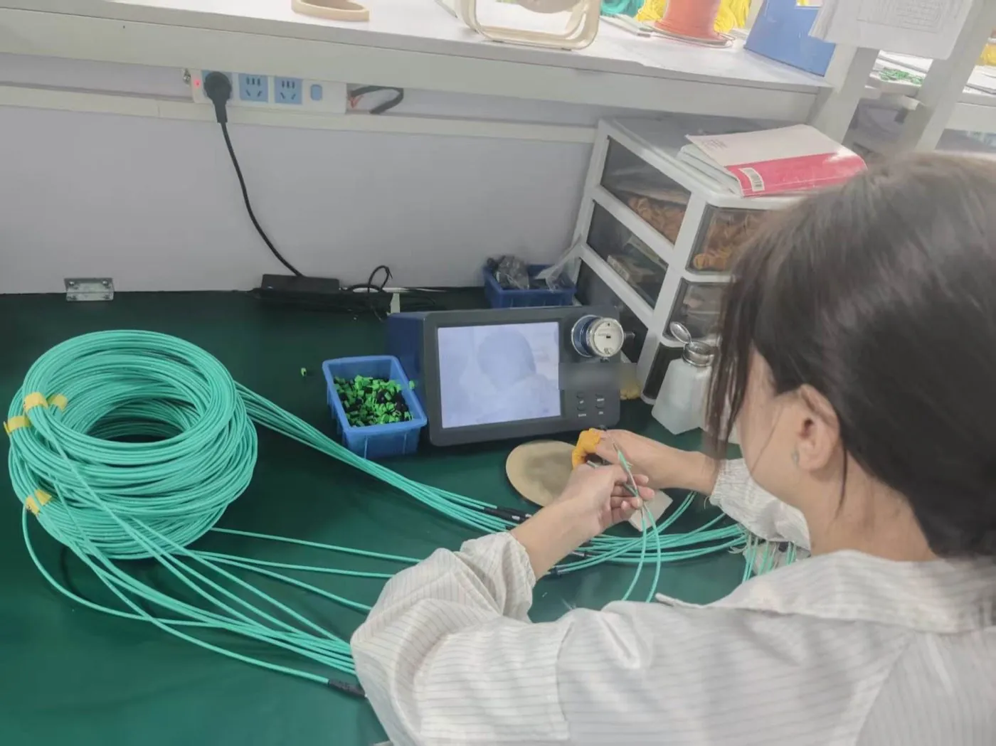
Breakout assemblies are terminated, inspected and packed in our own factory, and every batch has insertion loss and return loss test records. Before quoting, we check the drawing for fiber count, gender, polarity and leg lengths and raise questions in writing, so that the assembly fits the channel on arrival.

Technician checking a fiber connector end face on an inspection scope at a workbench
End-face inspection at the workbench in our own factory.

Which optical values are measured, at which wavelengths, and the report format are confirmed per line in your quotation. Our guides on reading a patch cord test report and inspecting and cleaning MPO/MTP connectors explain what to ask for and how to check assemblies on arrival.

What to Send in an MPO to LC Breakout RFQ

One line per breakout build, with the two ends described separately, gives the fastest and most accurate quote. The lines below show the format. They are examples, not real orders.

Example MPO to LC breakout RFQ lines (example, not a real order)
FieldExample A: Dallas, US colocationExample B: Toronto, CA enterpriseExample C: Rotterdam, NL data center
MPO endMPO-12, 8 fibers used, unpinnedMPO-12, 12 fibers, pinnedMPO-24, unpinned
Fiber and polishOM4, flat MPO, LC/UPCOS2, MPO/APC, LC/UPCOM4, flat MPO, LC/UPC
LC end4 × LC duplex6 × LC duplex12 × LC duplex
PolarityPer optic lane map (attached)Matches Type B trunk (drawing attached)Position-to-leg table attached
LegsJacketed, equal lengthJacketed, staggered to 1U port rowJacketed, staggered per drawing
Jacket and labelsOFNR; leg labels 1–4OFNR; customer label schemeLSZH; leg labels 1–12 plus end label
CommercialQuantity and required dateQuantity and required dateQuantity, required date, Incoterm

Send the lines with the form below, or email your BOM or drawing to sales@lumafyn.com. We reply with a written quotation that confirms optical values, test records, MOQ and lead time for each line.

FAQ

MPO to LC Breakout Cable Questions

What is an MPO to LC breakout cable?

It is a factory-terminated assembly with one MPO/MTP connector on one end and individual LC connectors, usually LC duplex, on the other. It converts a multi-fiber array port or trunk into separate duplex channels without a cassette.

How many LC connectors does an MPO-12 breakout have?

If all 12 fibers are used, six LC duplex legs (or twelve LC simplex). For 8-fiber parallel optics, only 8 of the 12 positions carry signals, so the breakout has four LC duplex legs and four unused positions.

Should the MPO end be pinned or unpinned?

Two mated MPO connectors need one pinned and one unpinned end. Choose the breakout's MPO gender to suit what it plugs into: a transceiver port, an adapter panel with a trunk behind it, or another assembly.

Are the LC ends UPC or APC?

Either can be built. Multimode LC ends are flat or PC polished. Singlemode LC ends are UPC unless the equipment or patch field is APC, in which case state LC/APC. Singlemode MPO ends are normally angle polished.

Is a breakout cable better than a cassette?

Neither is better in general. A breakout connects an MPO port straight to equipment with fewer mated pairs; a cassette gives you a labeled patch field and easier moves. Our breakout vs harness vs cassette guide explains when to use each.

Do you send test records with breakout cables?

Our own factory keeps insertion loss and return loss test records per batch. Which values, wavelengths and report format you receive is confirmed in your quotation.

Related Products, Guides and Sources

Related products and guides

Sources

Standards and public references describe definitions and industry practice; they are not Lumafyn product data. Optical values, MOQ and lead time for your order are confirmed in your quotation and test records.

Get a Quote